
- And Gate
- Nand Gate
- RS-Nor Latch
- B Flip Flop
- Xnor Gate
- Xor Gate
- BD n-switcher
- D Flip Flop
- JK Flip FLop
- Implies Gate
And Gate
Spoiler
Show

This gate sends out a signal if both inputs are on. Size:2x1x3
Spoiler
Show

Less common than the And gate, it is built the same except for a not gate, or inverter, at the output and it does not send out a signal if both inputs are on. Size:2x1x6
Spoiler
Show
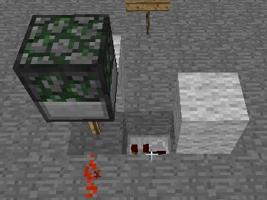
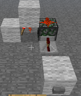
This gate allows pulses of power, such as a button press, something triggering a pressure plate, or something triggering the detector block, to become a continual power until it is reset. For the first circuit, the input is the Block Dispenser, or BD, the output is the redstone torch placed by the BD, and the reset is the block that the torch is on. Size: 1x3x1 The second circuit relies on the block above the torch and the redstone on the BD to keep the output on. Size: 3x2x2
Spoiler
Show

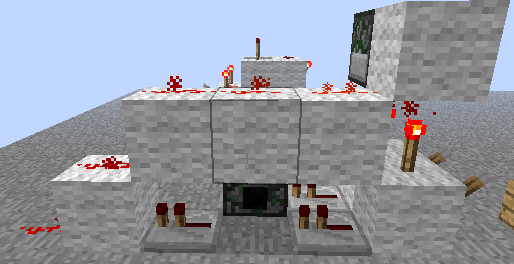
Credit for this insanely compact version goes to Battosay. A T Flip Flop changes its output from off to on ,and vice versa, every time the input switches state, i.e. the input goes on then off, the output turns on. the input goes on and off again, and the output turns off. This is achieved by placing a block that can transmit redstone power and a glass block in a block dispenser, hooking the input up to a not gate, and placing a torch underneath the block that will be placed. This can also be adapted to recognize a certain number of pulses by placing the conductive block in a later slot and filling the ones before it with glass. Size:2x2x4
Spoiler
Show


An Xnor Gate will output power if the inputs are equal, but will not output power when the outputs aren't equal. In this setup, it includes two of the earlier mentioned and gates, with one having the inputs inverted, and the other having them normally. Size:2x3x5
Spoiler
Show


This gate is the exact opposite of the Xnor gate, in that it will output power if both inputs are unequal, and not output power when both inputs are equal. I basically put a not gate at the output to invert the signal, so it is only one block larger than the Xnor gate. Size:2x3x6
Spoiler
Show

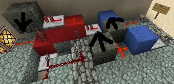
Congrats to Harcion for this neat little counter. Seeing as he is the creator, I should quote some of his description:
Harcion wrote:It has one input, one toggle and three outputs. Every time the toggle receives a pulse the input is routed to the next output in a cyclical manner. That is, the redstone current first goes through the 1st output then switches to the 2nd, then to the 3rd and then on the next toggle back to the 1st output.
In the picture, the input is to the right, the outputs on the other side and the toggle input is above the button. There is redstone on top of the blocks on top of the BD's, to activate them.
Each BD contains three blocks - one conductive (A) and two non-conductive (B,C). The first BD has them in the A,B,C order, the next one has C,A,B and the last one has B, C, A. In this case I used axles and fences for B and C and repeaters for A. Repeaters only work if you build it in the correct cardinal direction.
Either using more repeaters (because the outputs get tangled up otherwise), or having some space between the BD's, you can easily make an n-switcher for n <= 9 using the same concept.
Spoiler
Show


The purpose of this Flip Flop is as a memory cell. The output will be the opposite of the lever connected to the torch in the first two pictures, but if the other lever is on, the output will ignore any changes in the first lever. The first picture is 4x2x5, and has the input to the memory cell on (more or less) the same plane. The second picture is a vertical adaptation with a size of 2x4x5, and it allows fairly parallel circuits, spaced two or three blocks apart. The third and fourth pictures are designs created by Rasuth. They both use an And gate and an rs-nor latch, while capitalizing on the powering abilities of redstone and BDs to use the same current that triggers the BD in the And gate to also activate the clock. Size:3x3x7. The second one is 2x3x6
Spoiler
Show

Rasuth wrote:The JK-FF has 4 potential states, depending on the inputs J(ump) and K(ill) every clock pulse one of the following happens:
J=0, K=0 : keep state, Output stays the same.
J=1, K=0 : Jump, Output is set to true.
J=0, K=1 : Kill, Output is set to false.
J=1, K=1 : Trigger, Output changes state from false to true or vice versa.
This design by Rasuth uses a B-FF as internal memory cell and triggers it when (Clock AND ((J AND NOT(Q)) OR (K AND Q)) evaluates to true. Size: 6x3x11
Truthtable:
Q is the current output of the FF, Q+ is the output after the next clock pulse. T indicates wether the internal T-FF needs to be triggered or not.
J|K|Q|Q+|T = (Q XOR Q+)
0|0|0|0 |0
0|0|1|1 |0
0|1|0|0 |0
0|1|1|0 |1
1|0|0|1 |1
1|0|1|1 |0
1|1|0|1 |1
1|1|1|0 |1
Spoiler
Show

Rasuth wrote: The "Implies" gate outputs a current as long as the logical statement (A -> B) (read: "A implies B") holds true. This equivalent to the statement (B OR NOT(A)). In other words the output is only off, if A=1 and B=0. In all other cases the output is on.
Design by Rasuth. Size: 2x2x3